Intergrowth Family CIT-13
2-dimensional disorder of the units connecting ordered layers
Periodic Building Unit
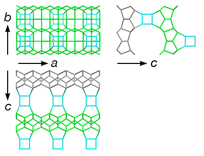
| Periodic Building Unit (PerBU): | CFI layer | |||||
| Layer symmetry | p m m 2 | |||||
| 2D cell parameters | a = 10.50 Å | b = 13.50 Å | gamma = 90° | Comment | To facilitate understanding of the connectivity patterns shown below, O atoms that connect to a single row of d4r units have been highlighted in the CFI layer shown to the right. |
|
Connecting unit
| Connecting unit | d4r |  |
|||
References
Connectivity pattern
Each CFI layer is generated from the previous one by a mirror plane. The CFI layers themselves are fully ordered in 3 dimensions. However, the rows of d4r unit connectors can be disordered along both b and c, making the disorder in this family 2-dimensional.
| Examples |
 |
Positions of d4r unit connectors in a row
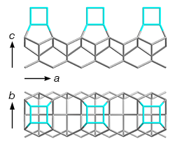
There are two possible positions for a row of d4r units above the CFI layer. The position of the first d4r unit (along a) determines the positions of all the other d4r units in that row.
|
| Examples |
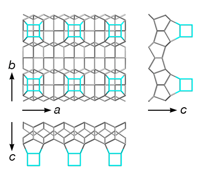 |
Disorder along b: layers formed by the rows d4r unit connectors
The arrangement of the rows of d4r units is not necessarily periodic along b. Each row can be the same as the neighboring one or shifted by 1/2a.
|