1-dimensional stacking disorder with two periodic building units
SBS-SBT-FAU-EMT Intergrowths
Periodic Building Units
Layer 2:
FAU layer
Layer symmetry
p -3 1 m
2D cell parameters
a = 17.22 Å
b = 17.22 Å
gamma = 120.0°
Layer 1:
SBS layer
Layer symmetry
p -3 1 m
2D cell parameters
a = 17.29 Å
b = 17.29 Å
gamma = 120.0°
Comment:
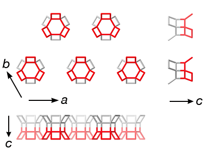
To facilitate understanding of the connectivity patterns shown below, the 6-rings that connect to the next layer have been highlighted in both layers. The SBS layer corresponds to the can layer and the FAU layer to the sod layer used by the authors.
References
Zeng, J., Lee, H., Jo, D., Mayoral, A. and Hong, S.B.
"Coupling different periodic building units for intergrowth zeolites"
J. Am. Chem. Soc. , 146, 13651-13657 (2024)
Connectivity pattern
There are two different PerBU's (layers), but both connect to the next layer in the same way. The 6-rings in the adjacent layers connect to form a hexagonal pattern of d6r units. The attached 4-rings on either side of the d6r units are related either by a local inversion center (i) or a local mirror plane (m). The layers are stacked along the [001] direction using the following connectivity patterns
Type
Comment
Image
1
local Inversion center
2
local mirror plane
Connections from SBS layer
Type
Layer 2
Comment
Image
1
SBS
SBS connection
2
SBS
SBT connection
1
FAU
2
FAU
Connections from FAU layer
Type
Layer 2
Comment
Image
1
SBS
2
SBS
1
FAU
FAU connection
2
FAU
EMT connection
Simplest ordered end members
The SBS layers are shown in blue (connection type 1) and green (connection type 2), and FAU layers in orange (connection type 1) and yellow (connection type 2). Adjacent layers generated by the same connectivity type (same basic color) are shown with different shades for clarity.