Newsam, J.M., Treacy, M.M.J., Koetsier, W.T. and de Gruyter, C.B.
"Structural characterization of zeolite beta"
Proc. R. Soc. Lond. A, 420, 375-405 (1988)
Connectivity pattern
Examples
The layers are stacked along the [001] direction using the following connectivity patterns
Symmetry Operation*
Translation*
Comment
Image
m
1/3 a
the next layer cannot be translated along a
m
-1/3 a
the next layer cannot be translated along a
m
1/3 b
the next layer cannot be translated along b
m
-1/3 b
the next layer cannot be translated along b
m
none
connectivity pattern for the next layer changes with each m operation
* relative to the previous layer
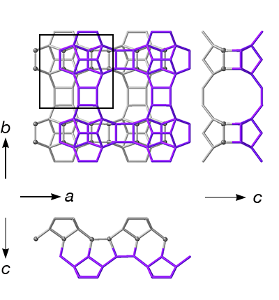
Short explanation: The "purple layer" is a mirror image of the previous layer (symmetry operation m) and is translated 1/3 of a unit cell along a. Note: The next layer cannot be translated along the same axis, e.g. a "purple" layer can only be followed by a yellow, blue or green layer.
Detailed Explanation: Each application of a mirror operation changes the pattern of the connecting T atoms. If they form rows along the a direction on the top surface of the previous layer, only translations of zero (green layer) or ±1/3 a (purple or brown layer) are possible. If they form rows along the b direction (gray spheres), only translations of zero (green layer) or ±1/3 b (yellow or blue layer) are possible. The connecting T atoms (those pointing up) from the top surface of the previous layer (gray layers) are highlighted as spheres in the examples to the right.
Effect on channel system
The disorder does not block the channel system
Simplest ordered end members
The color of each layer reflects the symmetry/translation operation used to generate it from the previous layer (see table above).
In this space group and setting, the PerBUs are stacked along [001] Adjacent layers generated by the same connectivity pattern (same basic color) are shown with different shades for clarity
Note: This polymorph corresponds to the ordered framework BEC