Intergrowth Family ECNU-23
2-dimensional disorder of the units connecting ordered layers
Periodic Building Unit
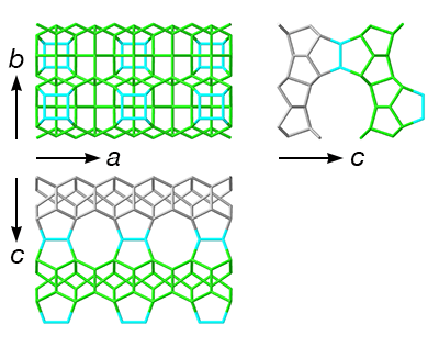
| Periodic Building Unit (PerBU): | CFI layer | |||||
| Layer symmetry | p m m 2 | |||||
| 2D cell parameters | a = 10.50 Å | b = 13.86 Å | gamma = 90° | Comment | To facilitate understanding of the connectivity patterns shown below, O atoms that connect to a single row of 4-ring units have been highlighted in the CFI layer shown to the right. |
|
Connecting unit
| Connecting unit | 4-ring |  |
|||
References
Connectivity pattern
Each CFI layer is generated from the previous one by a mirror plane. The CFI layers themselves are fully ordered in 3 dimensions. However, the rows of 4-ring unit connectors can be disordered along both b and c, making the disorder in this family 2-dimensional.
| Examples |
 |
Positions of 4-ring unit connectors in a row
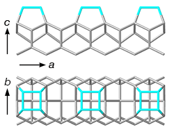
There are two possible positions for a row of 4-ring units above the CFI layer. The position of the first 4-ring unit (along a) determines the positions of all the other 4-ring units in that row.
|
| Examples |
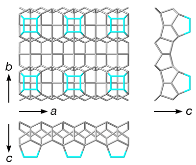 |
Disorder along b: layers formed by the rows 4-ring unit connectors
The arrangement of the rows of 4-ring units is not necessarily periodic along b. Each row can be the same as the neighboring one or shifted by 1/2a.
|